Half wave bridge rectifier circuit diagram Diode bridge rectifier ac to dc Diode bridge rectifier electrical4u
Introduction to Rectifier Diode Circuit Wokring and Its Applications
Introduction to rectifier diode circuit wokring and its applications Half wave bridge rectifier diagram Diode rectifier bridge dc ac
What should i consider when choosing the right diode…
Rectifier diode: function and circuitFord f650 ignition schematic What is the function of rectifier cheaper than retail price> buyRectifier circuits using diodes.
What is boost converter? circuit diagram and workingDiodes diode type electronics semiconductor symbols schematic circuit types component material junction combination known made Explain circuit diagram of bridge rectifierCircuit diagram of full rectifier.

Full bridge circuit diagram
Diode rectifier symbol circuit working applications itsRectifier circuit diode bridge schematic diagram function diodes figure transformer point current Diode bridge rectifierTypes different diode symbol diagram components symbols schematic electronics electrical wiring led circuit electronic component direction signal ac diagrams pasta.
A rectifier everyday low pricesSymbol-of-9-different-types-of-diode Diode diodes converter rectifier circuit applicationsRectifier bridge diode rectifiers circuits.

Mains noise eilimination
.
.

Rectifier Circuits Using Diodes

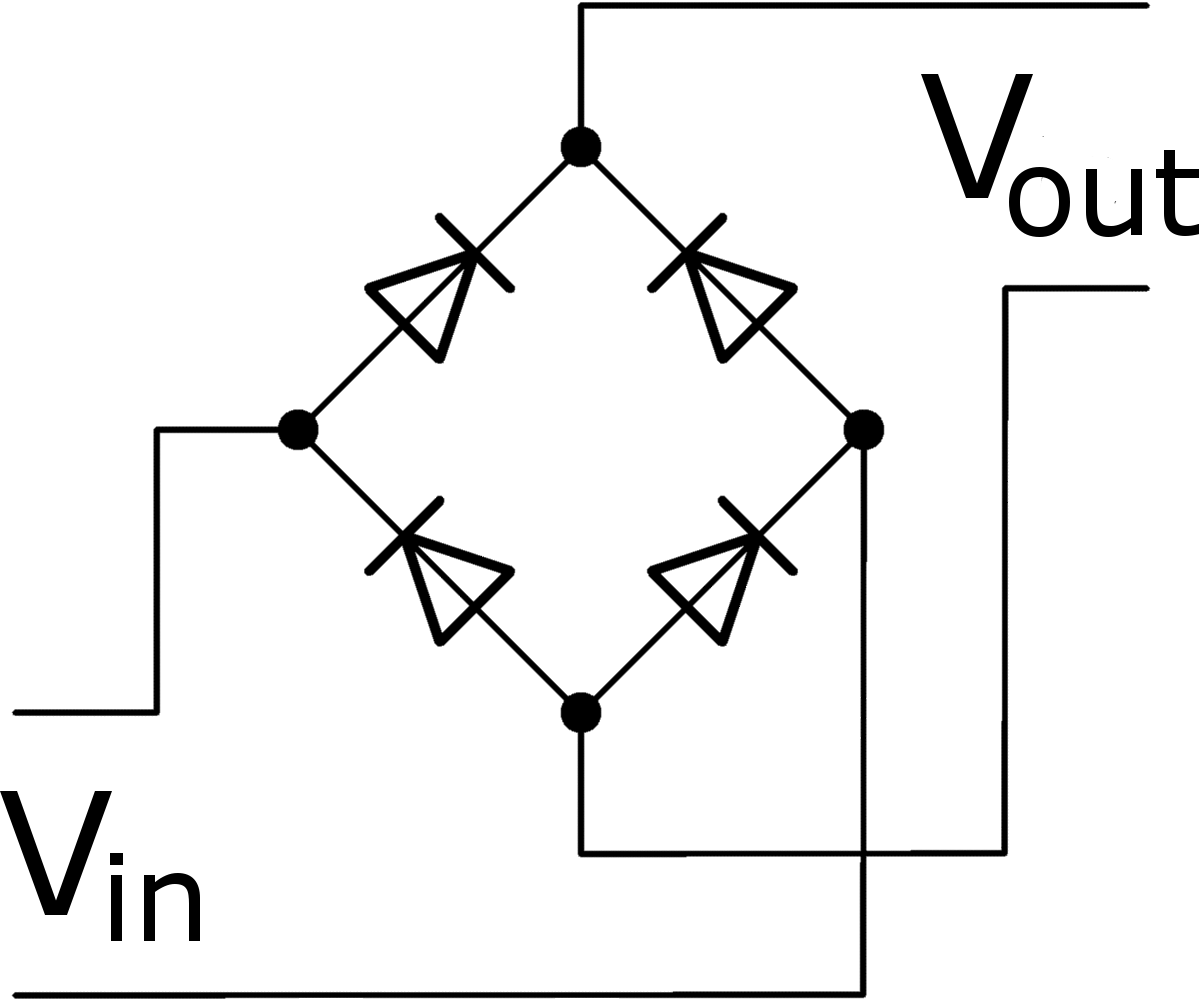
Diode Bridge Rectifier | Electrical4U

Full Bridge Circuit Diagram

Ford F650 Ignition Schematic

Half Wave Bridge Rectifier Diagram

Half Wave Bridge Rectifier Circuit Diagram

What is Boost Converter? Circuit Diagram and Working

Rectifier Diode: Function and Circuit - Utmel

mains noise eilimination | diyAudio